


Instrucciones de uso
- Clasificación:Quality center
- Tiempo de emisión:2019-09-16 00:00:00
- Visitas:0
INSTALLATION MANUAL
1 preface Introductio
This manual contains information regarding installation and safe handling of our company PV modules (hereafter is referred to as "module”).
The installation personnel shall be familiar with the mechanical and electrical requirement of PV system. The installation personnel shall conform to all safety precautions listed in this manual when installing the modules. Local laws and regulations shall also be followed in installations.
This product must be installed by a licensed electrician in accordance with the applicable electrical code (e.g. the NEC for the USA、CEC for Canada、PSE for Japan.).
Our company does not assume responsibility and expressly disclaims liability for loss, damage, or expense arising out of any violation of this manual.
This manual shall be properly kept for future reference (care and maintenance) and in case of sale or disposal of the module at the end of its useful life.
Our company reserves the ultimate right to interpretation of this installation manual.
Information contained within is subject to change without notice.
2 General
2.1 It requires specialized skills and knowledge for installation of solar photovoltaic systems. It shall be performed by qualified licensed professional installation personnel.
2.2 Installation shall be in accordance with the applicable electrical code .
2.3 All modules come with a permanently attached junction box. Our company can provide prefabricated cable appointed by customer.
2.4 The installation personnel shall assume the risk of all injury that might occur during installation, including, without limitation, the risk of electric shock.
2.5 Solar modules generate electricity if the front side is exposed in sunlight, with DC voltage higher than 30V. If modules are series connected, the total voltage shall be sum of individual voltage; if modules are parallel connected, the total current shall be sum of individual current.
2.6 Do not disconnect during load connection
2.7 Modules installed outdoor such as ground, roofs, vehicle or vessel. Appropriate support structure shall be designed by system designer or installer.
2.8 Do not disassemble modules or move parts of any nameplate or adhesion.
2.9 If modules are exposed to sunlight or other light sources, the risk of electric shock may occur when touching the electrical part of modules by occasion of DC current.
2.10 Do not use mirrors or lenses to focus sunlight on to modules, or let modules’ back be in direct exposure to the sunlight.
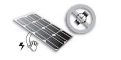
2.11Anything dropping on or covering modules is not allowed. Trampling, standing or walking on modules is prohibited.
2.12Do not pull or drag the modules by cables or connectors.


2.13 Direct handing of the electrical part of modules is prohibited. Be sure that using tools in line with the electrical installation insulation requirements for electrical connection.

2.14 Once PV systems need to integrate storage batteries, it shall follow the suggestions of battery manufacturers.
3 safety precaution
3.1 The module is considered to be in compliance with UL 1703 only when the module is mounted in the manner specified by the mounting instructions below.
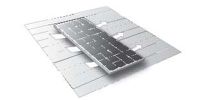
3.2 between PV module frame and the mounting surface may be required to prevent the junction box from touching the surface, and to circulate cooling air around the back of PV module. Spacing between PV modules must be a minimum of 1/8" (3.2 mm) to allow for thermal expansion. If the modules are to be installed on the roof or wall of a building, the stand-off method or the rack method is recommended.
3.3 The minimum spacing of 50mm (2”) is required between PV module and the mounting surface around the perimeter of PV module. Mounting hole size of each component is 9mm * 14mm. (Refer to Module Mounting Specifications). These are used for fixing PV modules to the supporting structure.
3.4 During transportation and installation, keeping children away from modules.
3.5 The modules are designed to fulfill the criteria of Application class A requirements according to IEC61730-1.Modules rated for use in application class A may be used in systems operating at greater than 50VDC or 240W, where general contact access is anticipated. Modules qualified for safety through IEC61730-1 and IEC61730-2 within application class A are considered to meet the requirements for safety class Ⅱ.In case of roof installation, PV module assembly shall be mounted on a fire resistant roof covering rated for the application. Modules are comprised of a glass front surface, polyethylene terephthalate (PET) back sheet with a Class C fire rating.
3.6 Modules shall be covered completely by non-transparent materials to prevent the current generated.
3.7 During transportation and installation, do not wear metal rings, bracelet, earrings, nose rings, lip rings or other metal accessories.
3.8 Employing equipments, connectors, wires and brackets which match solar power system. In a particular system, be sure to employ the same type of modules.
3.9 For a non-integral module or panel,the assembly is to be mounted over a fire resistant roof covering rated for the application.
3.10 This cable is suitable for applications where wiring is exposed to the direct rays of the sun. The maximum and minimum outer diameters of the cable that may be used with the cable connector are 8 mm and 6 mm respectively .
3.11 In normal outdoor conditions, the generated current and voltage maybe different from the parameters listed in Table. Parameter table is measured under standard test conditions (STC), so concerning settling parameters of other parts of photovoltaic power generation system, such as rated voltage, the wire capacity, fuse, the controller capacity and module power output, it shall refer to the short-circuit current (Isc) and open circuit voltage (Voc) noted on modules’ label, with the redundancy value of 125% for design and installation.
3.12 Under normal conditions, a photovoltaic module is likely to experience conditions that produce more current and/or voltage than reported at standard test conditions. The values of ISC and VOC marked on this module should be multiplied by a factor of 1.25 when determining component voltage ratings, conductor ampacities, overcurrent device ratings, and size of controls connected to the PV output.
3.13 Do not touch terminals while a module is exposed to light. Provide suitable guards to prevent yourself contacting directly with 45 VDC or greater to avoid the hazard of electric shock or injury.
4 CERTIFICATION
The SM-XXX Modules comply with the requirements of IEC61215, IEC61730-1 and IEC61730-2.5 Tools & Materials for Installation 5.1 Screwdriver
5.2 Wrench
5.3 Mounting bracket
5.4 Stainless steel screws, nuts, washers, clips and other accessories
6 Mechanical installation
6.1 Location Selection
(1) A suitable installation location shall be carefully selected for modules.
(2) In the northern hemisphere, modules had better be installed facing south direction; in the
southern hemisphere, modules had better be installed facing north.
(3) Inclination angle of optimal installation can be referred to the standard solar photovoltaic installation instruction or a reliable solar systems installation company.
(4) Modules shall be installed in the position of full sun exposure and not be obscured at any time.
(5) Do not place the modules where it is easy to produce or gather combustible gases.
6.2 Appropriate bracket selection
System designer or installer shall keep loads calculation, and select the appropriate brackets complying with the attached manual guidance and safety regulations.
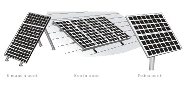
6.3 Ground-mounted Appropriate PV system installation height shall be guaranteed to prevent the lower part of the modules from covering by heavy snow for a long time in winter; and also to ensure that the lower part of modules being installed high enough in case of sand or wind damage, and plants or trees block.
6.4 Roof installation (1) Being installed on roof or building, modules shall be securely fixed so as not to be destroyed because of strong winds or heavy snow.
(2) Proper ventilation shall be guaranteed for cooling off (minimum interval between modules
and mounting surface shall be 10cm).
(3) Concerning roof-mounting, the roof structure shall be guaranteed. In addition, the roof shall be properly sealed to prevent the house leaking.
(4) In some cases, a special bracket shall be applied.
(5) It may affect fire resistance of the house if roof-mounted; The module must be mounted over a fire resistant roof covering rated for the application.
(6) Installing is prohibited in strong wind.
6.3 Installation of pillarsAn appropriate mounting structure, which is able to withstand the local expected maximum wind force, of modules and pillars shall be designed and selected.
6.6 General Principles of Mechanical installation(1) Drilling on glass surface of modules is prohibited, otherwise it invalidates warranty.
(2) Any module without a frame (laminate) shall not be considered to comply with the requirements of UL 1703 unless the module is mounted with hardware that has been tested and evaluated with the module under this standard or by a field Inspection certifying that the installed module complies with the requirements of UL 1703.
(3) Drilling of additional mounting holes on frames of modules is prohibited, otherwise it invalidates warranty.
(4) Modules shall be installed by 8 symmetric mounting holes inside frames. Using corrosion-proof screws (M8) in the existing installing holes in the module frame. The frame of each Module has 8 mounting holes used to secure the Modules to supporting structure.
(5) Moving modules by dragging junction box or cables is prohibited.
(6) Throwing modules is prohibited.
(7) Note: inappropriate transportation or installation may cause damage.
(8) The high level of load condition is applicable to the installation in harsher environmental conditions such as storm, heavy snow, etc: the maximum static load on the back of the Modules is 5400Pa,and it’s the same pressure on the front side of the module.
7 Electrical Connections
7.1 Please read the electrical wiring drawings carefully before wiring the PV system.
7.2 Module specification normal: such as SM660-250W, the open circuit voltage: 38.1V, short circuit current: 8.80A, working voltage: 30.7V, the operating current: 8.15A, specific parameters refer to the detailed product specification. Other product information please refer to the attached
7.3 Open the connection box of the control system and connect the cabled from the PV arrays to the connection box in accordance with the installation indication of the PV control systems.
7.4 The connection of modules: in accordance with system design, requirements of output voltage and current, modules can be series or parallel connected by their connecting wires; The maximum number of modules in series (N)= the maximum system voltage Vmax / (the open circuit voltage Voc of one single module *1.2); the number of modules in parallel is one under standard test conditions.
7.5 Connection of modules and junction box: the modules series and junction boxes shall be connected by DC cable. Cross-sectional area and connector capacity of the cable shall meet the maximum system short-circuit current (it is recommended 4mm2 for the cable cross-sectional area
of an individual module, connector rated current greater than 10A), otherwise the cable and connector would be overheating because of strong circuit. The cable type is PV1-F。Please note that the maximum temperature of cables shall be 90℃, and the maximum temperature of connector shall be 120℃.
7.6 All module frames should be grounded for safety. Aluminum frame and brackets of modules must be grounded with two ground holes of each module, which is marked on frames (it is recommended that each series/parallel of modules should be grounded once). Ground hole diameter of 4 mm.The specific location of the grounding holes can be seen as the figure below. Modules and ground cables shall be connected perfectly by wiring nose.The recommended size of the ground wire is 4‐14mm2 (cc) copper wires. The rating temperature should be above120℃。

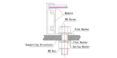
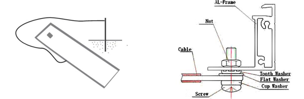
7.7 Where common grounding hardware (nuts, bolts, star washers, spilt-ring lock washers, flat washers and the like) is used to attach a listed grounding/bonding device,the attachment must be made in conformance with the grounding device manufacturer’s instructions.M8 bolt (material shall be 304 stainless steel) and connections will be installed in the frame of the connection nose. Next is the flat washers, star washer, finally is the nut, to ensure that the whole assembly of reliable grounding, as shown in figure.

7.8 The electrical connection shall conform to local electrical laws and regulations.
7.9 Common hardware items such as nuts, bolts, star washers, lock washers and the like have not been evaluated for electrical conductivity or for use as grounding devices and should be used only for maintaining mechanical connections and holding electrical grounding devices in the proper position for electrical conductivity. Such devices, where supplied with the module and evaluated through the requirements in UL 1703, may be used for grounding connections in accordance with the instructions provided with the module.
7.10 Modules are equipped with bypass diodes,The bypass diode type is 20SQ045(SM series) .; improper installation may damage diodes, cables or wiring box.The cable type is PV1-F。
7.11 The end with junction box shall be installed facing up in case of the connector drowned.
7.12 Please wrap the connectors after taking out the modules without immediate installation so as to prevent damage caused by wind or rain. Use of lubricant for connectors is prohibited, because it leads fracture of connectors.
7.13 Remove waterproof rubber rings of the junction box and connectors is prohibited.
7.14 Use of diesel oil for heating is strictly prohibited at installation site, which may lead to connector failure because the gas after combustion of diesel and other petroleum products may cause the wiring boxes cracking.
7.15 Under normal conditions, a photovoltaic module is likely to experience conditions that produce more current and/or voltage than reported at standard test conditions. Accordingly, the values of Isc and Voc marked on this module should be multiplied by a factor of 1,25 when determining component voltage ratings, conductor current ratings, fuse sizes, and size of controls connected to the PV output.
7 Maintenance
8.1 Check all electrical connections to ensure that there is no open-circuit and well-connected.
(1) Check the open circuit voltage of each module:
(2) Modules shall be completely covered by non-transparent material.
(3) Disconnect the wire of both ends of modules.
(4) Remove the non-transparent material on the modules; check and measure the terminal open circuit voltage.
(5) If the measured voltage is reduced by 1/4, bypass diode is supposed to be damaged.
Please test the bypass diode performance.
8.2 Our company is recommending the following maintenance measures to ensure the best performance of modules:
1) If necessary, please clean glass surface of modules by soft sponge or wiping cloth with water. A mild without abrasive cleaning agent can be used to remove stubborn dirt.
2) Mechanical and electrical checks are required every six months so as to ensure the modules’ connectors clean and reliable connected.
3) If there is any question, modules shall be inspected by qualified personnel.
4) Please note that all maintenance instructions, such as brackets, charging rectifier, inverters and batteries, shall be complied.
ANNEX A Date sheet for all module types
SM672-280 Series:
|
Parameters |
SM672-275 |
SM672-280 |
SM672-285 |
SM672-290 |
SM672-295 |
SM672-300 |
SM672-305 |
SM672-310 |
SM672-315 |
SM672-320 |
SM672-325 |
|
|
Peak power Pm(W) |
275±5% |
280±5% |
285±5% |
290±5% |
295±5% |
300±5% |
305±5% |
310±5% |
315±5% |
320±5% |
325±5% |
|
|
Open circuit voltage Voc(V) |
44.3V |
44.5V |
44.8V |
44.8V |
45.0V |
45.0V |
45.5V |
45.8V |
46.2V |
46.4V |
46.4V |
|
|
Max.power voltage Vmp(V) |
35.8V |
36.5V |
36.7V |
36.7V |
36.8V |
36.8V |
37.0V |
37.1V |
37.3V |
37.4V |
37.4V |
|
|
Max.power current Imp(A) |
7.69A |
7.67A |
7.77A |
7.90A |
8.02A |
8.15A |
8.24A |
8.36A |
8.45A |
8.56A |
8.69A |
|
|
Short circuit current Isc(A) |
8.31A |
8.39A |
8.48A |
8.60A |
8.82A |
9.26A |
9.41A |
9.61A |
9.71A |
9.75A |
9.81A |
|
|
Dimensions(L*W*H) |
1957*992*40 |
|||||||||||
|
Weigh(kg) |
21 |
|||||||||||
|
Max.over-current (A) |
14 |
|||||||||||
|
Max.system voltage (V) |
1000V DC |
|||||||||||
|
Application Class |
Class A |
|||||||||||
|
Mono crystalline silicon solar cell |
156*156*0.19mm |
|||||||||||
|
No.of cells and connections |
72series |
|||||||||||
|
No. of bypass diodes |
3 |
|||||||||||
|
Bypass diode rating (A) |
20A |
|||||||||||
|
Bypass diode max. Junction temperature(℃) |
200 |
|||||||||||
|
Bypass diode thermal resistance(℃/W) |
2.0 |
|||||||||||
|
STC |
Irradiance:1000W/m2,Cell temperature:25℃,AM:1.5 |
|||||||||||
|
Maximum No.of series connection |
18 |
18 |
18 |
18 |
18 |
18 |
18 |
18 |
18 |
17 |
17 |
|
|
Maximum No.of parallel connection |
1 |
|||||||||||
SM660-230 Series:
|
Parameters |
SM660-230 |
SM660-235 |
SM660-240 |
SM660-245 |
SM660-250 |
SM660-255 |
SM660-260 |
SM660-265 |
SM660-270 |
|
|
Peak power Pm(W) |
230±5% |
235±5% |
240±5% |
245±5% |
250±5% |
255±5% |
260±5% |
265±5% |
270±5% |
|
|
Open circuit voltageVoc(V) |
36.8V |
37.4V |
37.4V |
37.4V |
38.1V |
38.3V |
38.7V |
38.9V |
39.0V |
|
|
Max.power voltage Vmp(V) |
29.7V |
30.2V |
30.2V |
30.2V |
30.7V |
30.9V |
31.2V |
31.3V |
31.5V |
|
|
Max.power current Imp(A) |
7.75A |
7.79A |
7.94A |
8.11A |
8.15A |
8.25A |
8.33A |
8.47A |
8.57A |
|
|
Short circuitcurrentIsc(A) |
8.30A |
8.40A |
8.58A |
8.76A |
8.80A |
8.90A |
9.01A |
9.22A |
9.30A |
|
|
Dimensions(L*W*H) |
1640*992*40 |
|||||||||
|
Weigh(kg) |
18 |
|||||||||
|
Max.over-current (A) |
14 |
|||||||||
|
Max.system voltage (V) |
1000V DC |
|||||||||
|
Application Class |
Class A |
|||||||||
|
Mono crystalline silicon solar cell |
156*156*0.19mm |
|||||||||
|
No.of cells and connections |
60 series |
|||||||||
|
No.of bypass diodes |
3 |
|||||||||
|
Bypass diode rating (A) |
20A |
|||||||||
|
Bypass diode max. Junction temperature(℃) |
200 |
|||||||||
|
Bypass diode thermal resistance(℃/W) |
2.0 |
|||||||||
|
STC |
Irradiance:1000W/m2,Cell temperature:25℃,AM:1.5 |
|||||||||
|
Maximum No.of series connection |
22 |
22 |
22 |
22 |
21 |
21 |
21 |
21 |
21 |
|
|
Maximum No.of parallel connection |
1 |
|||||||||
SM654-210 Series:
|
Parameters |
SM654-210 |
SM654-215 |
SM654-220 |
SM654-225 |
SM654-230 |
SM654-235 |
SM654-240 |
SM654-245 |
|
|
Peak power Pm(W) |
210±5% |
215±5% |
220±5% |
225±5% |
230±5% |
235±5% |
240±5% |
245±5% |
|
|
Open circuit voltage Voc(V) |
33.5V |
33.8V |
34.0V |
34.3V |
34.5V |
34.6V |
34.6V |
34.8V |
|
|
Max.power voltage Vmp(V) |
26.7V |
26.9V |
27.0V |
27.2V |
27.3V |
27.3V |
27.4V |
27.5V |
|
|
Max.power current Imp(A) |
7.87A |
8.00A |
8.15A |
8.27A |
8.42A |
8.61A |
8.76A |
8.91A |
|
|
Short circuit currentIsc(A) |
8.56A |
8.71A |
8.91A |
9.09A |
9.25A |
9.30A |
9.36A |
9.41A |
|
|
Dimensions(L*W*H) |
1482*992*40 |
||||||||
|
Weigh(kg) |
16.5 |
||||||||
|
Max.over-current (A) |
14 |
||||||||
|
Max.system voltage (V) |
1000V DC |
||||||||
|
Application Class |
Class A |
||||||||
|
Mono crystalline silicon solar cell |
156*156*0.19mm |
||||||||
|
No.of cells and connections |
54series |
||||||||
|
No.of bypass diodes |
3 |
||||||||
|
Bypass diode rating (A) |
20A |
||||||||
|
Bypass diode max. Junction temperature(℃) |
200 |
||||||||
|
Bypass diode thermal resistance(℃/W) |
2.0 |
||||||||
|
STC |
Irradiance:1000W/m2,Cell temperature:25℃,AM:1.5 |
||||||||
|
Maximum No.of series connection |
24 |
24 |
24 |
24 |
24 |
24 |
24 |
24 |
|
|
Maximum No.of parallel connection |
1 |
||||||||
Escanee el código QR con su teléfono móvil


Copyright 2019 Simax (Suzhou) Green New Energy Co.,ltd. 苏ICP备11054210号-1 Powered by: www.300.cn